<?xml version="1.0" encoding="utf-8"?><feed xmlns="http://www.w3.org/2005/Atom" ><generator uri="https://jekyllrb.com/" version="3.10.0">Jekyll</generator><link href="https://tahamousa2023-prog.github.io/feed.xml" rel="self" type="application/atom+xml" /><link href="https://tahamousa2023-prog.github.io/" rel="alternate" type="text/html" /><updated>2026-06-22T13:27:10+02:00</updated><id>https://tahamousa2023-prog.github.io/feed.xml</id><title type="html">Taha Mohammed</title><subtitle>Mechatronics &amp; Computational Engineering · TU Berlin · Robotics · AI · 3D Reconstruction</subtitle><author><name>Taha Mohammed</name><email>taha.mousa2023@gmail.com</email></author><entry><title type="html">Path Matters: What We Built, What We Found, and What Comes Next</title><link href="https://tahamousa2023-prog.github.io/posts/2026/04/path-matters-final-report/" rel="alternate" type="text/html" title="Path Matters: What We Built, What We Found, and What Comes Next" /><published>2026-04-14T00:00:00+02:00</published><updated>2026-04-14T00:00:00+02:00</updated><id>https://tahamousa2023-prog.github.io/posts/2026/04/path-matters-final-report</id><content type="html" xml:base="https://tahamousa2023-prog.github.io/posts/2026/04/path-matters-final-report/"><![CDATA[<p>After six months of work, the Path Matters project is submitted. This post is a summary of what we built, the results we got, and what I personally learned from it. The full report is available through TU Berlin.</p>

<p>The project ran as an automation engineering course at TU Berlin (WiSe 25/26), supervised by Adam Altenbuchner at the Institut für Werkzeugmaschinen und Fabrikbetrieb. Five engineers: Artem Balatsiuk, Aziz Louati, Haroun Lallouche, Taha Mohammed (me), and Ziad Abouhalawa. The question we were trying to answer was simple to state and genuinely hard to answer: does the choice and sequence of camera viewpoints significantly affect the quality of 3D reconstruction from a robotic scanner?</p>

<p><strong>What we built</strong></p>

<p>The system is a modular pipeline connecting a UR5e robot arm in NVIDIA Isaac Sim, controlled through ROS2 Humble and MoveIt2, to three reconstruction models (VGGT, Fast3R, SAM3D), and an evaluation pipeline using ICP and BUFFER-X to measure alignment quality against ground-truth meshes. My responsibility was trajectory planning — designing the motion strategies, implementing the ROS2 control pipeline, and running the scanning experiments.</p>

<p>The pipeline has four independent modules that communicate through a shared directory structure: trajectory (viewpoint generation and execution), data (image export and point cloud management), reconstruction (wrapping all three models behind a common interface), and evaluation (ICP registration and metric computation). This design made it possible to swap any component and compare results systematically.</p>

<p><strong>Reconstruction: VGGT wins clearly</strong></p>

<p>We evaluated VGGT, Fast3R, and SAM3D on 28 objects drawn from Isaac Sim synthetic data, Google Scanned Objects, T-LESS and Linemod benchmarks, and real-world hand-held captures. Each method received the same set of 12 images from a fixed hemispheric trajectory, and we measured ICP Fitness and RMSE after registration against the ground-truth mesh.</p>

<p>VGGT: Fitness 0.93, RMSE 0.002 m. Fast3R: Fitness 0.89, RMSE 0.010 m. SAM3D: Fitness 0.91, RMSE 0.008 m. All three finish inference in under 10 seconds on our RTX A6000. VGGT wins on both metrics and became the primary reconstruction backbone for all subsequent experiments.</p>

<p>One practical complication: VGGT and Fast3R produce reconstructions in an arbitrary scene-relative scale with no absolute metric information. Before registration, you need to estimate the scale factor. We used a median consensus approach combining three estimators — bounding box diagonal ratio, PCA axis length ratios, and convex hull volume ratio. In extreme mismatch cases, this improved ICP Fitness from 0.0 to 1.0. Without scale correction, the alignment metrics are meaningless.</p>

<p><strong>Registration: ICP outperforms BUFFER-X here, but context matters</strong></p>

<p>For our evaluation setting — preprocessed point clouds with reasonable initial alignment — ICP with FPFH initialisation outperformed BUFFER-X on all metrics: Fitness 0.87 versus 0.81, RMSE 0.0041 m versus 0.0063 m, recall above 0.8 threshold at 78.6% versus 67.9%. BUFFER-X is faster (1.8 s versus 3.2 s) and does not require a coarse initial alignment, which makes it useful when RANSAC fails. The two methods are complementary rather than competing.</p>

<p><strong>Trajectory: camera orientation is the biggest lever</strong></p>

<p>I ran five scanning patterns (Lawnmower, Zigzag, Hemisphere, Spiral, Random) under two camera orientation strategies. Approach 1: camera always points straight down. Approach 2: camera dynamically points toward the detected object centre at every waypoint.</p>

<p>Approach 1 mean ICP Fitness across all patterns: 0.68. Approach 2 mean: 0.79. The improvement was consistent across every pattern without changing the number of viewpoints or the trajectory geometry. The best single result was Hemisphere with Approach 2: Fitness 0.86, RMSE 0.015 m.</p>

<p>This was the clearest finding of the trajectory experiments: camera orientation matters more than trajectory pattern at this scale. Which pattern you use — lawnmower, hemisphere, spiral — has a secondary effect compared to whether the camera is actually looking at the object from each position. The implementation cost of dynamic object-pointing orientation is modest (slightly more complex IK solutions, around 5% IK failure rate versus 0% for fixed downward, and 0.5 s longer stabilisation pause), and the quality gain is substantial.</p>

<p><strong>Reinforcement learning: proximity shaping solves the sparse reward problem</strong></p>

<p>The RL component uses Isaac Lab with 16 parallel UR5e environments, PPO, and an 86-dimensional state space including joint positions, camera pose, coverage percentage, and an 8x8 downsampled voxel coverage map. The agent selects continuous joint position deltas; images are captured automatically every 20 steps.</p>

<p>First experiment (exp_06): coverage rewards only, no signal toward the scanning volume. Task success rate: 0.4%. The robot occasionally stumbled into good positions by chance but could not reproduce the behaviour.</p>

<p>Second experiment (exp_07): added three proximity shaping rewards providing a continuous gradient toward the workspace — a proximity gradient toward the volume centre, a binary reward for being inside the workspace bounds, and a dot-product reward for facing the volume. Task success rate: 45.2%. Coverage: 75% or more per episode. Versus random exploration: 3.6x higher coverage, 75%+ versus 20.6%.</p>

<p>The practical lesson is that proximity shaping is not a nice-to-have: it is necessary for this environment. Without a gradient guiding the robot toward the scanning volume, the coverage rewards never activate and learning stalls. The agent needs to learn to get close before it can learn to scan.</p>

<p>There is a known limitation: the RL agent maximises geometric voxel coverage (frustum-based), not actual reconstruction quality. Coverage and ICP Fitness are correlated but not identical. The obvious next step — and the open research question the project leaves behind — is to replace the geometric coverage metric with direct ICP Fitness or VGGT confidence as the reward signal.</p>

<p><strong>What I would do differently</strong></p>

<p>The preprocessing pipeline (RANSAC plane removal, DBSCAN clustering) failed on roughly 15% of objects — either removing part of the object or not finding the table plane. These failures propagated into degraded scale estimation and registration. More robust preprocessing, or replacing it with a learned segmentation approach like YOLO-based semantic crop, would have improved the tail of the distribution.</p>

<p>The RL training stability was also not fully resolved. The exp_07 task success rate peaks near 100% around iteration 1500 before settling at 40–45%. For deployment, you would need to select the peak checkpoint rather than the final one. Entropy coefficient scheduling and learning rate decay would likely improve convergence.</p>

<p><strong>What comes next</strong></p>

<p>For me personally, this project confirmed that I want to keep working on robotic perception and learning-based control, specifically the problems around sim-to-real transfer and direct optimisation of reconstruction quality through robot behaviour. The trajectory planning work connects directly to the reward signal design question in the RL component, and both connect to the calibration work I did at Fraunhofer IPK. I am looking for a PhD position where I can develop these threads further.</p>

<p>The full report, code, and results are available on request. If you are working on related problems and want to discuss, feel free to reach out.</p>]]></content><author><name>Taha Mohammed</name><email>taha.mousa2023@gmail.com</email></author><category term="Isaac Sim" /><category term="UR5e" /><category term="ROS2" /><category term="VGGT" /><category term="BUFFER-X" /><category term="ICP" /><category term="Reinforcement Learning" /><category term="PPO" /><category term="3D Reconstruction" /><category term="TU Berlin" /><category term="Path Matters" /><summary type="html"><![CDATA[After six months of work, the Path Matters project is submitted. This post is a summary of what we built, the results we got, and what I personally learned from it. The full report is available through TU Berlin.]]></summary></entry><entry><title type="html">VGGT → Open3D → BUFFER-X → ICP: Full Registration Pipeline</title><link href="https://tahamousa2023-prog.github.io/posts/2026/03/vggt-bufferx-icp-pipeline/" rel="alternate" type="text/html" title="VGGT → Open3D → BUFFER-X → ICP: Full Registration Pipeline" /><published>2026-03-17T00:00:00+01:00</published><updated>2026-03-17T00:00:00+01:00</updated><id>https://tahamousa2023-prog.github.io/posts/2026/03/vggt-open3d-bufferx-icp-pipeline</id><content type="html" xml:base="https://tahamousa2023-prog.github.io/posts/2026/03/vggt-bufferx-icp-pipeline/"><![CDATA[<p>This post documents the full 4-stage registration pipeline developed as 
part of the <strong>Path Matters</strong> project at TU Berlin. Starting from a VGGT 
reconstruction, we manually clean and align the point cloud using Open3D, 
then run BUFFER-X for coarse global registration, and finally refine with 
ICP — producing quantitative alignment metrics at every stage.</p>

<video width="100%" controls="">
  <source src="/files/pipeline_demo.mp4" type="video/mp4" />
  Your browser does not support the video tag.
</video>

<hr />

<h2 id="overview">Overview</h2>

<p>A key challenge in robotic 3D reconstruction is aligning a reconstructed 
point cloud to a ground truth model for quality evaluation. This pipeline 
solves that end-to-end:</p>

<p><strong>The 4-stage pipeline:</strong></p>

<p>Raw reconstruction → Manual crop + alignment → BUFFER-X initial alignment → ICP final refinement → Metrics</p>

<p><strong>Test object:</strong> Air conditioner control unit — real-world scan from our 
<a href="https://github.com/MIT-SPARK/BUFFER-X">Reallife Dataset</a></p>

<hr />

<h2 id="system-setup">System Setup</h2>

<table>
  <thead>
    <tr>
      <th>Component</th>
      <th>Detail</th>
    </tr>
  </thead>
  <tbody>
    <tr>
      <td>Reconstruction</td>
      <td>VGGT (Visual Geometry Grounded Transformer)</td>
    </tr>
    <tr>
      <td>Manual alignment</td>
      <td>Open3D interactive crop + point picking</td>
    </tr>
    <tr>
      <td>Initial registration</td>
      <td>BUFFER-X (zero-shot, threedmatch model)</td>
    </tr>
    <tr>
      <td>Final refinement</td>
      <td>ICP Point-to-Plane</td>
    </tr>
    <tr>
      <td>Environment</td>
      <td><code class="language-plaintext highlighter-rouge">bufferx_o3d</code> conda environment</td>
    </tr>
    <tr>
      <td>Dataset</td>
      <td>Reallife_Dataset — air_conditioner_control_camera3</td>
    </tr>
  </tbody>
</table>

<hr />

<h2 id="how-to-run">How to Run</h2>

<h3 id="activate-environment">Activate environment</h3>

<div class="language-plaintext highlighter-rouge"><div class="highlight"><pre class="highlight"><code>conda activate bufferx_o3d
</code></pre></div></div>

<h3 id="run-the-full-pipeline">Run the full pipeline</h3>

<div class="language-plaintext highlighter-rouge"><div class="highlight"><pre class="highlight"><code>python3 /home/AP_PathMatters/path_matters/haroun/Pipeline/cc_bufferx_pipeline_package/run_cc_bufferx_pipeline.py \
  --recon-root /home/AP_PathMatters/path_matters/datasets/Reallife_Dataset_Haroun_Aziz/scenes-others_SUBSAMPLED \
  --gt-root /home/AP_PathMatters/path_matters/datasets/Reallife_Dataset_Haroun_Aziz/scenes-others_SUBSAMPLED \
  --output-base /home/AP_PathMatters/path_matters/haroun/runs \
  --run-name test_bufferx_before_icp \
  --bufferx-root /home/AP_PathMatters/BUFFER-X \
  --bufferx-env bufferx_o3d \
  --scene-names air_conditioner_control_camera3 \
  --recon-candidates recon_generated/vggt/points.ply \
  --manual-mode require \
  --manual-backend open3d \
  --open3d-crop \
  --open3d-pre-scale aabb_diag \
  --open3d-with-scaling \
  --save-viz \
  --show-final-viz
</code></pre></div></div>

<hr />

<h2 id="stage-1--raw-overlay">Stage 1 — Raw Overlay</h2>

<p>
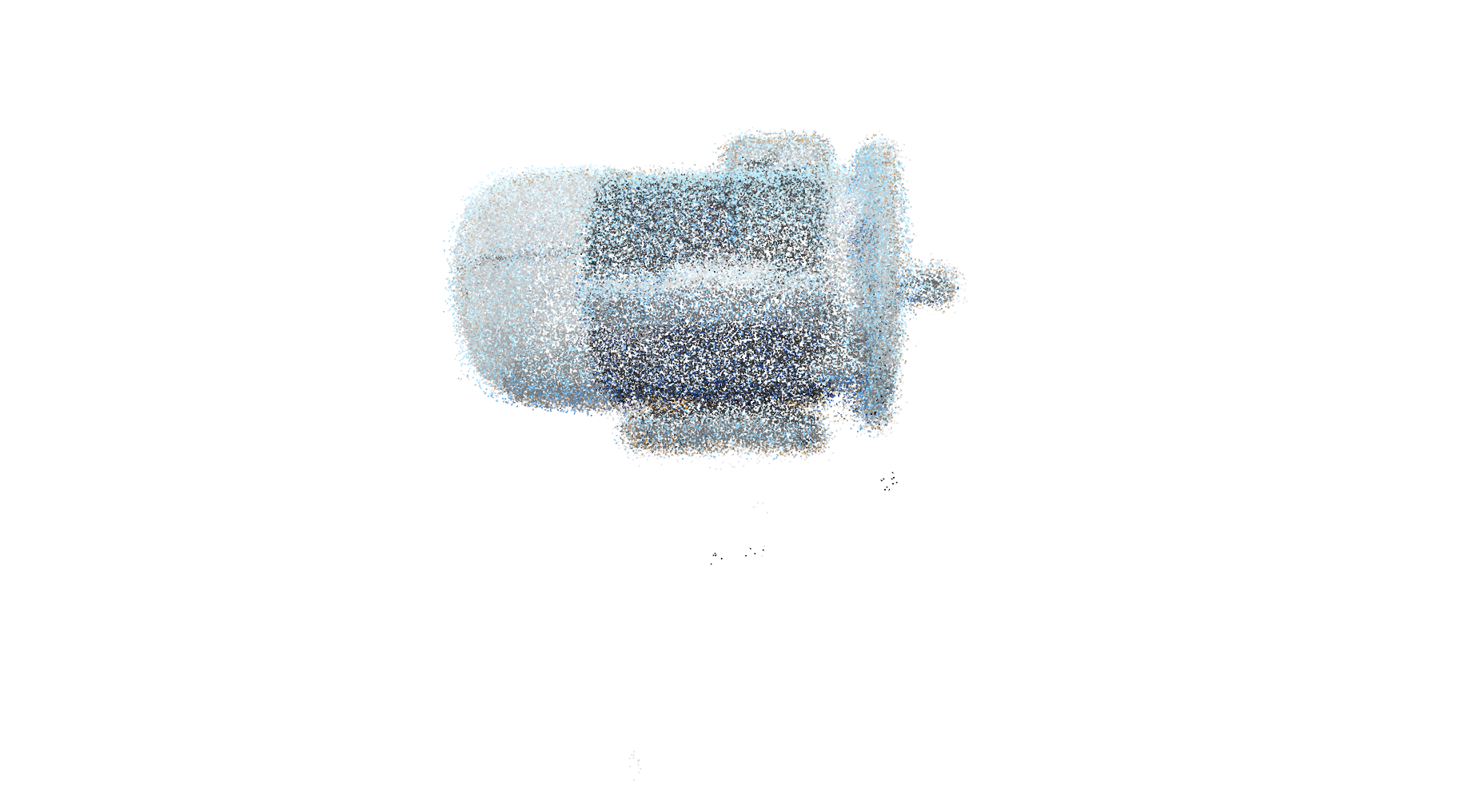
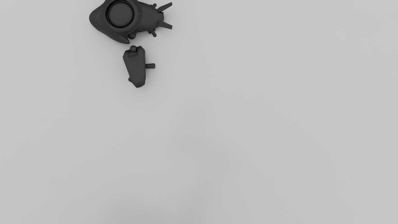
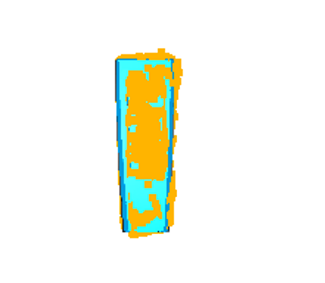
The raw VGGT reconstruction and ground truth are loaded and overlaid 
before any alignment. The two clouds are in completely different 
coordinate frames at this stage.</p>

<p><img src="/images/pipeline_01_raw.png" width="100%" /></p>
<p style="font-size: 13px;"><em>Stage 1: Raw overlay — reconstruction (yellow) vs ground truth (cyan), unaligned</em></p>

<hr />

<h2 id="stage-2--manual-open3d-alignment">Stage 2 — Manual Open3D Alignment</h2>

<p>Before BUFFER-X runs, the reconstruction is manually cleaned and 
coarsely aligned using Open3D’s interactive tools.</p>

<h3 id="step-1--crop-window">Step 1 — Crop window</h3>

<p>The Open3D crop window removes background clutter from the reconstruction, 
isolating only the target object.</p>

<p><strong>Controls used:</strong></p>
<ul>
  <li><code class="language-plaintext highlighter-rouge">Y</code> twice — align view</li>
  <li><code class="language-plaintext highlighter-rouge">K</code> — enter selection mode</li>
  <li>Drag mouse — rectangle selection around object</li>
  <li><code class="language-plaintext highlighter-rouge">C</code> — crop</li>
  <li><code class="language-plaintext highlighter-rouge">Q</code> — continue</li>
</ul>

<h3 id="step-2--point-picking">Step 2 — Point picking</h3>

<p>After cropping, at least 3 corresponding points are picked manually 
between source and target to compute an initial transform.</p>

<p><strong>Controls used:</strong></p>
<ul>
  <li><code class="language-plaintext highlighter-rouge">Shift + Left Click</code> — pick point</li>
  <li><code class="language-plaintext highlighter-rouge">Shift + Right Click</code> — undo</li>
  <li>Minimum 3 points in source, then 3 matching points in target</li>
  <li><code class="language-plaintext highlighter-rouge">Q</code> — continue</li>
</ul>

<p><img src="/images/pipeline_02_manual.png" width="100%" /></p>
<p style="font-size: 13px;"><em>Stage 2: After manual crop and Open3D point-picking alignment</em></p>

<p><strong>Key setting — pre-scale:</strong>
<code class="language-plaintext highlighter-rouge">--open3d-pre-scale aabb_diag</code> automatically scales the reconstruction 
to roughly match the ground truth bounding box diagonal before point 
picking — critical when VGGT output scale differs from real-world scale.</p>

<hr />

<h2 id="stage-3--buffer-x-initial-alignment">
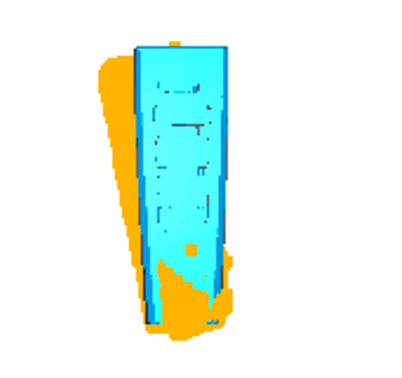
Stage 3 — BUFFER-X Initial Alignment</h2>

<p>
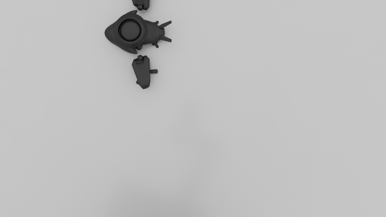
After manual alignment, BUFFER-X performs global registration to 
refine the coarse initial pose into a reliable starting point for ICP.</p>

<p><img src="/images/pipeline_03_bufferx.png" width="100%" /></p>
<p style="font-size: 13px;"><em>Stage 3: After BUFFER-X global registration</em></p>

<h3 id="buffer-x-results">BUFFER-X Results</h3>

<table>
  <thead>
    <tr>
      <th>Metric</th>
      <th>Value</th>
    </tr>
  </thead>
  <tbody>
    <tr>
      <td><strong>Source points</strong></td>
      <td>28,032</td>
    </tr>
    <tr>
      <td><strong>Target points</strong></td>
      <td>30,000</td>
    </tr>
    <tr>
      <td><strong>Voxel size</strong></td>
      <td>0.0051 m</td>
    </tr>
    <tr>
      <td><strong>Sphericity</strong></td>
      <td>0.0246</td>
    </tr>
    <tr>
      <td><strong>Inference time</strong></td>
      <td>~0.51 s</td>
    </tr>
    <tr>
      <td><strong>Model</strong></td>
      <td>threedmatch (zero-shot)</td>
    </tr>
  </tbody>
</table>

<p><strong>Sphericity of 0.025</strong> confirms the object has strong geometric 
structure — low sphericity means the point cloud has distinctive 
directional features, making descriptor matching reliable.</p>

<hr />

<h2 id="stage-4--icp-final-refinement">
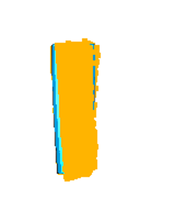
Stage 4 — ICP Final Refinement</h2>

<p>
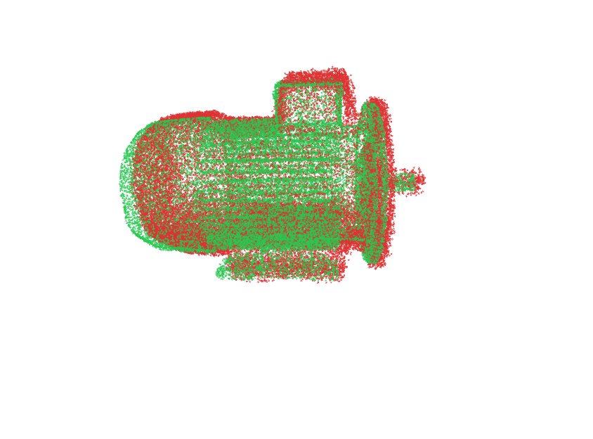
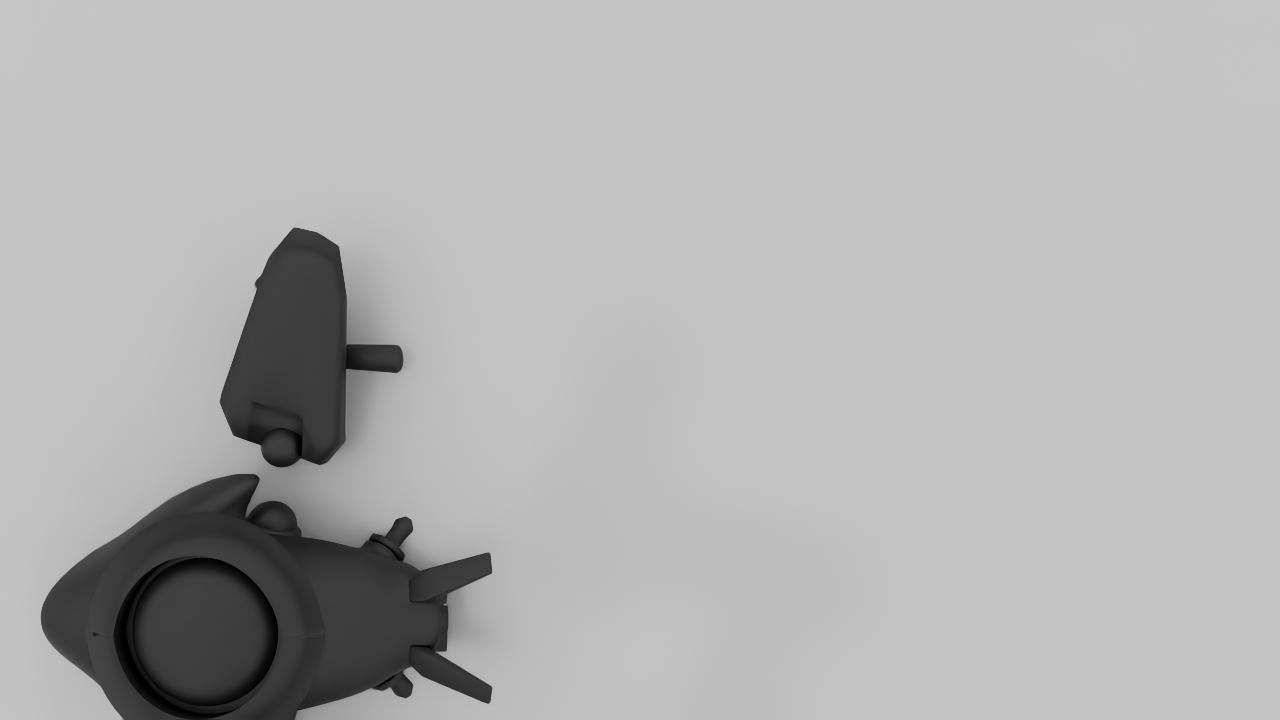
BUFFER-X output is used as the initial transform for ICP, which 
iteratively refines the alignment to sub-centimeter precision.</p>

<p><img src="/images/pipeline_04_icp.png" width="100%" /></p>
<p style="font-size: 13px;"><em>Stage 4: Final result after ICP Point-to-Plane refinement</em></p>

<h3 id="icp-results">ICP Results</h3>

<table>
  <thead>
    <tr>
      <th>Metric</th>
      <th>Value</th>
      <th>Interpretation</th>
    </tr>
  </thead>
  <tbody>
    <tr>
      <td><strong>ICP Fitness</strong></td>
      <td><strong>0.817</strong></td>
      <td>81.7% of points matched ✅</td>
    </tr>
    <tr>
      <td><strong>ICP Inlier RMSE</strong></td>
      <td><strong>0.0287 m</strong></td>
      <td>2.87 cm on matched points</td>
    </tr>
    <tr>
      <td><strong>Overall RMSE</strong></td>
      <td><strong>0.051 m</strong></td>
      <td>5.1 cm including outliers</td>
    </tr>
    <tr>
      <td><strong>Median distance</strong></td>
      <td><strong>0.026 m</strong></td>
      <td>2.6 cm — half of points within this</td>
    </tr>
    <tr>
      <td><strong>P90 distance</strong></td>
      <td><strong>0.067 m</strong></td>
      <td>90% of points within 6.7 cm</td>
    </tr>
    <tr>
      <td><strong>P95 distance</strong></td>
      <td><strong>0.090 m</strong></td>
      <td>95% of points within 9.0 cm</td>
    </tr>
    <tr>
      <td><strong>Max distance</strong></td>
      <td><strong>0.284 m</strong></td>
      <td>Worst-case outlier</td>
    </tr>
    <tr>
      <td><strong>ICP mode</strong></td>
      <td>Point-to-Plane</td>
      <td>Standard for smooth surfaces</td>
    </tr>
    <tr>
      <td><strong>Point count</strong></td>
      <td>28,555</td>
      <td>Total evaluated correspondences</td>
    </tr>
  </tbody>
</table>

<h3 id="what-these-numbers-mean">What these numbers mean</h3>

<p><strong>Fitness of 0.817</strong> is a strong result — 81.7% of reconstruction 
points found a valid match in the ground truth model. This is 
significantly better than our earlier Baby Yoda test (0.33) because 
the background was properly removed before registration.</p>

<p><strong>Inlier RMSE of 2.87 cm</strong> represents the average error on matched 
points — comparable to the BUFFER-X 3DMatch benchmark result of 
5.79 cm RTE, confirming the pipeline generalizes well to real-world 
industrial objects.</p>

<p><strong>Median distance of 2.6 cm</strong> means half of all reconstruction 
points lie within 2.6 cm of the ground truth surface — good accuracy 
for a real-world scan of an industrial object.</p>

<hr />

<h2 id="all-4-stages-side-by-side">All 4 Stages Side by Side</h2>

<p><a href="/images/01_raw_overlay.png" target="_blank">
  <img src="/images/01_raw_overlay.png" width="100%" />
</a></p>
<p style="font-size: 13px;"><em>1. Raw — click to enlarge</em></p>

<p><a href="/images/02_manual_overlay.png" target="_blank">
  <img src="/images/02_manual_overlay.png" width="100%" />
</a></p>
<p style="font-size: 13px;"><em>2. Manual — click to enlarge</em></p>

<p><a href="/images/03_bufferx_overlay.png" target="_blank">
  <img src="/images/03_bufferx_overlay.png" width="100%" />
</a></p>
<p style="font-size: 13px;"><em>3. BUFFER-X — click to enlarge</em></p>

<p><a href="/images/04_icp_overlay.png" target="_blank">
  <img src="/images/04_icp_overlay.png" width="100%" />
</a></p>
<p style="font-size: 13px;"><em>4. ICP Final — click to enlarge</em></p>

<hr />

<h2 id="pipeline-output-structure">Pipeline Output Structure</h2>

<p>After the run, all outputs are saved automatically:</p>

<div class="language-plaintext highlighter-rouge"><div class="highlight"><pre class="highlight"><code>runs/test_bufferx_before_icp/air_conditioner_control_camera3/
├── raw/
│   ├── recon_input.ply       ← original VGGT reconstruction
│   └── gt_input.ply          ← ground truth model
├── manual/
│   ├── recon_cropped.ply     ← after Open3D crop
│   └── recon_manual.ply      ← after point-picking alignment
├── bufferx/
│   ├── init_transform.txt    ← BUFFER-X 4x4 transform matrix
│   └── init_summary.json     ← BUFFER-X metrics
├── icp/
│   ├── icp_transform.txt     ← ICP 4x4 transform matrix
│   ├── icp_summary.json      ← ICP metrics
│   └── aligned_source_icp.ply← final aligned reconstruction
├── viz/
│   ├── 01_raw_overlay.png
│   ├── 02_manual_overlay.png
│   ├── 03_bufferx_overlay.png
│   └── 04_icp_overlay.png
└── scene_status.json         ← overall run status
</code></pre></div></div>

<p><strong>Check run status:</strong></p>

<div class="language-plaintext highlighter-rouge"><div class="highlight"><pre class="highlight"><code>cat runs/test_bufferx_before_icp/air_conditioner_control_camera3/scene_status.json
</code></pre></div></div>

<hr />

<h2 id="why-buffer-x-before-icp-matters">Why BUFFER-X Before ICP Matters</h2>

<table>
  <thead>
    <tr>
      <th>Approach</th>
      <th>ICP Result</th>
    </tr>
  </thead>
  <tbody>
    <tr>
      <td><strong>ICP alone (no init)</strong></td>
      <td>Diverges — wrong local minimum</td>
    </tr>
    <tr>
      <td><strong>Manual init only</strong></td>
      <td>Better but still rough</td>
    </tr>
    <tr>
      <td><strong>BUFFER-X init → ICP</strong></td>
      <td>Fitness 0.817, RMSE 2.87 cm ✅</td>
    </tr>
  </tbody>
</table>

<p>BUFFER-X provides a reliable coarse alignment that puts ICP in the 
correct convergence basin. Without it, ICP gets stuck in the wrong 
local minimum and produces garbage results regardless of how many 
iterations it runs.</p>

<hr />

<h2 id="challenges-and-solutions">Challenges and Solutions</h2>

<p><strong>Challenge 1 — Scale mismatch</strong>
VGGT reconstruction scale differs from real-world ground truth scale.
Solution: <code class="language-plaintext highlighter-rouge">--open3d-pre-scale aabb_diag</code> automatically estimates and 
applies a scale correction before point picking.</p>

<p><strong>Challenge 2 — Background clutter</strong>
Raw VGGT output includes table, walls, and surrounding environment.
Solution: Open3D interactive crop isolates only the target object.</p>

<p><strong>Challenge 3 — Coordinate frame mismatch</strong>
VGGT and ground truth use different coordinate conventions.
Solution: Manual point picking establishes 3D correspondences that 
BUFFER-X uses to compute the correct initial transform.</p>

<p><strong>Challenge 4 — Low overlap regions</strong>
Some parts of the air conditioner were not captured from all angles.
Solution: P95 metric (9.0 cm) identifies these outlier regions 
separately from the well-aligned core (median 2.6 cm).</p>

<hr />

<h2 id="key-takeaway">Key Takeaway</h2>

<p>The <strong>BUFFER-X → ICP pipeline achieves 81.7% fitness and 2.87 cm 
inlier RMSE</strong> on a real-world industrial object — without any 
domain-specific retraining. The pipeline is generalizable: the same 
workflow works on Isaac Sim synthetic data and real-world scans.</p>

<p>The ICP Fitness and RMSE scores produced by this pipeline can feed 
directly into our <strong>PPO reinforcement learning reward function</strong>, 
giving the RL agent a quantitative signal for reconstruction quality 
at each viewpoint.</p>

<hr />

<h2 id="next-steps">Next Steps</h2>

<ul>
  <li>Test on multiple objects from the dataset</li>
  <li>Compare BUFFER-X → ICP vs ICP-only baseline quantitatively</li>
  <li>Integrate pipeline output as RL reward signal in Isaac Lab</li>
  <li>Automate the crop step using SAM3D segmentation masks</li>
</ul>

<hr />

<h2 id="resources">Resources</h2>

<ul>
  <li><a href="/portfolio/path-matters/">Path Matters Project Overview</a></li>
  <li><a href="/posts/2026/03/bufferx-registration/">BUFFER-X Integration Post</a></li>
  <li><a href="/posts/2026/03/trajectory-planning/">Trajectory Planning Post</a></li>
  <li><a href="https://github.com/MIT-SPARK/BUFFER-X">BUFFER-X GitHub</a></li>
  <li><a href="http://www.open3d.org/docs/release/">Open3D Documentation</a></li>
  <li><a href="https://arxiv.org/abs/2503.11651">VGGT Paper</a>
```</li>
</ul>

<hr />

<p><strong>After committing — do these 3 things:</strong></p>

<p><strong>1 — Upload the 4 visualization images to <code class="language-plaintext highlighter-rouge">images/</code>:</strong>
```
pipeline_01_raw.png       ← viz/01_raw_overlay.png
pipeline_02_manual.png    ← viz/02_manual_overlay.png
pipeline_03_bufferx.png   ← viz/03_bufferx_overlay.png
pipeline_04_icp.png       ← viz/04_icp_overlay.png</p>]]></content><author><name>Taha Mohammed</name><email>taha.mousa2023@gmail.com</email></author><category term="BUFFER-X" /><category term="ICP" /><category term="Open3D" /><category term="VGGT" /><category term="Point Cloud" /><category term="3D Reconstruction" /><category term="TU Berlin" /><category term="Path Matters" /><category term="Registration" /><summary type="html"><![CDATA[This post documents the full 4-stage registration pipeline developed as part of the Path Matters project at TU Berlin. Starting from a VGGT reconstruction, we manually clean and align the point cloud using Open3D, then run BUFFER-X for coarse global registration, and finally refine with ICP — producing quantitative alignment metrics at every stage.]]></summary></entry><entry><title type="html">BUFFER-X: Zero-Shot Point Cloud Registration in Isaac Sim</title><link href="https://tahamousa2023-prog.github.io/posts/2026/03/bufferx-registration/" rel="alternate" type="text/html" title="BUFFER-X: Zero-Shot Point Cloud Registration in Isaac Sim" /><published>2026-03-16T00:00:00+01:00</published><updated>2026-03-16T00:00:00+01:00</updated><id>https://tahamousa2023-prog.github.io/posts/2026/03/bufferx-registration</id><content type="html" xml:base="https://tahamousa2023-prog.github.io/posts/2026/03/bufferx-registration/"><![CDATA[<p><img src="/images/bufferx.gif" width="50%" /></p>
<p style="font-size: 13px;"><em>BUFFER-X Point Cloud Registration</em></p>

<p>As part of the <strong>Path Matters</strong> project at TU Berlin, this week I integrated 
<strong>BUFFER-X</strong> into our robotic 2D→3D reconstruction pipeline. BUFFER-X is a 
zero-shot point cloud registration method published as an 
<a href="https://github.com/MIT-SPARK/BUFFER-X">ICCV 2025 Highlight paper by MIT SPARK Lab</a>. 
It aligns two 3D point clouds into the same coordinate frame without any 
retraining or fine-tuning — across any scene or sensor type.</p>

<hr />

<h2 id="video-walkthrough">Video Walkthrough</h2>

<iframe width="560" height="315" src="https://www.youtube.com/embed/vGlQuBhjrPI" frameborder="0" allowfullscreen=""></iframe>

<hr />

<h2 id="the-problem-we-were-solving">The Problem We Were Solving</h2>

<p>Our pipeline uses a <strong>UR5e robot arm</strong> with a simulated <strong>Basler camera</strong> in 
<strong>NVIDIA Isaac Sim</strong> to capture multiple views of an object and reconstruct it 
in 3D. The reconstruction methods we tested — VGGT, Fast3R, and SAM3D — each 
produce point clouds in their own coordinate frames.</p>

<p>The challenge: <strong>ICP (Iterative Closest Point)</strong> alignment was failing because 
it had no reliable initial pose to start from. Without a good starting point, 
ICP diverges and gives wrong results.</p>

<p><strong>BUFFER-X solves this</strong> by providing a robust initial alignment before ICP runs.</p>

<hr />

<h2 id="where-buffer-x-fits-in-our-pipeline">Where BUFFER-X Fits in Our Pipeline</h2>

<p>Isaac Sim Scene → Basler Camera Capture → .PLY Export + Ground Truth Pose → 2D→3D Reconstruction → Preprocessing → <strong>BUFFER-X Initial Alignment</strong> → ICP Refinement → Fitness / RMSE Score → RL Reward Signal</p>

<hr />

<h2 id="what-is-buffer-x">What is BUFFER-X?</h2>

<p>BUFFER-X (Balanced Unified Feature-based Framework for Extended Registration) 
works in two stages:</p>

<ol>
  <li><strong>Descriptor stage</strong> — extracts local geometric features using a PointNet++ backbone with multi-scale grouping</li>
  <li><strong>Pose estimation stage</strong> — uses RANSAC or KISS-Matcher to find the optimal 6-DoF rigid transformation T ∈ SE(3)</li>
</ol>

<p>Key facts:</p>
<ul>
  <li>Only <strong>0.91M trainable parameters</strong> — extremely lightweight</li>
  <li><strong>~1 second</strong> per point cloud pair</li>
  <li>Trained once on indoor RGB-D data — works on outdoor LiDAR, synthetic Isaac Sim data, and more</li>
  <li><strong>ICCV 2025 Highlight</strong> · MIT SPARK Lab</li>
</ul>

<hr />

<h2 id="benchmark-results--3dmatch-indoor-dataset">Benchmark Results — 3DMatch Indoor Dataset</h2>

<p>I ran the full 3DMatch benchmark (1623 point cloud pairs) on our machine 
with an NVIDIA RTX A6000.</p>

<table>
  <thead>
    <tr>
      <th>Metric</th>
      <th>Result</th>
    </tr>
  </thead>
  <tbody>
    <tr>
      <td><strong>Recall</strong></td>
      <td>97.1%</td>
    </tr>
    <tr>
      <td><strong>RMSE Recall</strong></td>
      <td>95.2%</td>
    </tr>
    <tr>
      <td><strong>RTE</strong></td>
      <td>5.79 cm</td>
    </tr>
    <tr>
      <td><strong>RRE</strong></td>
      <td>1.80°</td>
    </tr>
    <tr>
      <td><strong>Failed pairs</strong></td>
      <td>47 / 1623</td>
    </tr>
    <tr>
      <td><strong>Inference time</strong></td>
      <td>~0.89 s per pair</td>
    </tr>
    <tr>
      <td><strong>Total runtime</strong></td>
      <td>28 minutes</td>
    </tr>
  </tbody>
</table>

<h3 id="why-did-47-pairs-fail">Why did 47 pairs fail?</h3>

<p><strong>1. Symmetric scenes (majority of failures)</strong>
These have RRE near 90°, 125°, or exactly 180° — the scene geometry is 
rotationally symmetric (empty corridors, white walls, repetitive patterns). 
No registration method can reliably distinguish these orientations.</p>

<p><strong>2. Low-overlap pairs</strong>
The two scans share very little overlapping geometry. With insufficient 
matching surface, no reliable transformation can be estimated.</p>

<p>These are fundamental data challenges, not model failures.</p>

<hr />

<h2 id="custom-test--isaac-sim-basler-camera">Custom Test — Isaac Sim Basler Camera</h2>

<p>I tested BUFFER-X on our own dataset: a <strong>Baby Yoda figurine</strong> scanned 
in Isaac Sim using a simulated Basler camera.</p>

<p><strong>Setup:</strong></p>
<ul>
  <li>Ground truth: <code class="language-plaintext highlighter-rouge">Baby_Yoda.ply</code> — 10,000 points, clean object, no color</li>
  <li>Reconstruction: <code class="language-plaintext highlighter-rouge">points.ply</code> — 100,000 points, full scene with RGB color</li>
</ul>

<p><strong>Results:</strong></p>

<table>
  <thead>
    <tr>
      <th>Metric</th>
      <th>Value</th>
    </tr>
  </thead>
  <tbody>
    <tr>
      <td><strong>Fitness</strong></td>
      <td>0.3342</td>
    </tr>
    <tr>
      <td><strong>RMSE</strong></td>
      <td>0.0287 m (2.87 cm)</td>
    </tr>
  </tbody>
</table>

<h3 id="before-alignment">Before Alignment</h3>

<p><img src="/images/before1.png" alt="Before alignment" /></p>

<h3 id="after-alignment">After Alignment</h3>

<p><img src="/images/After1.png" alt="After alignment" /></p>

<h3 id="why-is-fitness-033">Why is Fitness 0.33?</h3>

<p>The Fitness score of 0.33 means 33% of points were matched — which looks 
low but has a clear explanation: <code class="language-plaintext highlighter-rouge">points.ply</code> contains 100,000 points 
including the <strong>full Isaac Sim scene background</strong> (table, walls, floor), 
while <code class="language-plaintext highlighter-rouge">Baby_Yoda.ply</code> is a clean 10,000-point isolated object model.</p>

<p>The background clutter counts as unmatched points, pulling Fitness down. 
The <strong>RMSE of 2.87 cm on matched points</strong> shows the object itself aligned 
correctly — confirmed visually in the After image above.</p>

<p><strong>Next step:</strong> run our preprocessing pipeline (background removal, 
outlier filtering) on <code class="language-plaintext highlighter-rouge">points.ply</code> before comparison.</p>

<hr />

<h2 id="key-takeaway">Key Takeaway</h2>

<p>BUFFER-X gives ICP a reliable initial pose — without it, ICP was diverging 
on our Isaac Sim data. The zero-shot capability means it works on our 
completely unseen Isaac Sim Basler camera data without any retraining, 
which is exactly what our pipeline needs.</p>

<p>The Fitness and RMSE scores output by BUFFER-X can also feed directly into 
our <strong>PPO reinforcement learning reward function</strong> — replacing the current 
geometric heuristics with a direct alignment quality signal.</p>

<hr />

<h2 id="tools--setup">Tools &amp; Setup</h2>

<table>
  <thead>
    <tr>
      <th>Component</th>
      <th>Version</th>
    </tr>
  </thead>
  <tbody>
    <tr>
      <td>OS</td>
      <td>Ubuntu 22.04 LTS</td>
    </tr>
    <tr>
      <td>Python</td>
      <td>3.8</td>
    </tr>
    <tr>
      <td>PyTorch</td>
      <td>1.9.1+cu111</td>
    </tr>
    <tr>
      <td>CUDA</td>
      <td>11.1</td>
    </tr>
    <tr>
      <td>GPU</td>
      <td>NVIDIA RTX A6000 (49GB)</td>
    </tr>
    <tr>
      <td>Open3D</td>
      <td>0.13.0</td>
    </tr>
  </tbody>
</table>

<hr />

<h2 id="resources">Resources</h2>

<ul>
  <li><a href="https://github.com/MIT-SPARK/BUFFER-X">BUFFER-X GitHub</a></li>
  <li><a href="https://arxiv.org/abs/2503.07940">BUFFER-X Paper on arXiv</a></li>
  <li><a href="http://3dmatch.cs.princeton.edu/">3DMatch Dataset</a></li>
</ul>]]></content><author><name>Taha Mohammed</name><email>taha.mousa2023@gmail.com</email></author><category term="Isaac Sim" /><category term="Point Cloud" /><category term="3D Reconstruction" /><category term="ROS2" /><category term="TU Berlin" /><category term="Robotics" /><category term="BUFFER-X" /><summary type="html"><![CDATA[BUFFER-X Point Cloud Registration]]></summary></entry><entry><title type="html">UR5e Multi-View Trajectory Planning for 3D Reconstruction in Isaac Sim</title><link href="https://tahamousa2023-prog.github.io/posts/2026/03/trajectory-planning/" rel="alternate" type="text/html" title="UR5e Multi-View Trajectory Planning for 3D Reconstruction in Isaac Sim" /><published>2026-03-16T00:00:00+01:00</published><updated>2026-03-16T00:00:00+01:00</updated><id>https://tahamousa2023-prog.github.io/posts/2026/03/trajectory-planning</id><content type="html" xml:base="https://tahamousa2023-prog.github.io/posts/2026/03/trajectory-planning/"><![CDATA[<p><img src="/images/trajectory_demo.gif" alt="Trajectory Demo" /></p>

<p>As part of the <strong>Path Matters</strong> project at TU Berlin, this post documents 
the first complete pipeline run: a UR5e robot arm executes a planned 
multi-view camera trajectory in Isaac Sim, captures images from 7 
viewpoints, and saves them for 3D reconstruction. The system runs 
entirely in simulation using ROS2, MoveIt2 and Isaac Sim.</p>

<hr />

<h2 id="overview">Overview</h2>

<p>The core question of our <strong>Path Matters</strong> project is:</p>

<blockquote>
  <p>How do different viewpoint sequences and trajectory strategies affect 3D reconstruction quality, completeness and efficiency?</p>
</blockquote>

<p>This post documents the <strong>first building block</strong> — getting the UR5e 
to autonomously move to planned viewpoints and capture images. 
Everything runs in simulation before transferring to the real robot.</p>

<hr />

<h2 id="system-architecture">System Architecture</h2>

<p>Three components run simultaneously, each in its own terminal:</p>

<table>
  <thead>
    <tr>
      <th>Component</th>
      <th>Tool</th>
      <th>Purpose</th>
    </tr>
  </thead>
  <tbody>
    <tr>
      <td>Simulation</td>
      <td>NVIDIA Isaac Sim</td>
      <td>Physics + robot + camera</td>
    </tr>
    <tr>
      <td>Motion Planning</td>
      <td>ROS2 Humble + MoveIt2</td>
      <td>IK solving + collision checking</td>
    </tr>
    <tr>
      <td>Trajectory Control</td>
      <td>Python (ROS2 node)</td>
      <td>Waypoints + image capture</td>
    </tr>
    <tr>
      <td>Robot</td>
      <td>UR5e collaborative arm</td>
      <td>6-DOF manipulation</td>
    </tr>
    <tr>
      <td>Camera</td>
      <td>Simulated Basler RGB-D</td>
      <td>Image acquisition</td>
    </tr>
    <tr>
      <td>Scene</td>
      <td>17_12_robot_plane_graph.usd</td>
      <td>Environment + object</td>
    </tr>
  </tbody>
</table>

<hr />

<h2 id="how-to-run--step-by-step">How to Run — Step by Step</h2>

<h3 id="terminal-1--launch-isaac-sim">Terminal 1 — Launch Isaac Sim</h3>

<p>Open a terminal and run:</p>

<div class="language-plaintext highlighter-rouge"><div class="highlight"><pre class="highlight"><code>conda deactivate
cd isaacsim/_build/linux-x86_64/release
./isaac-sim.sh
</code></pre></div></div>

<p>Open scene: <code class="language-plaintext highlighter-rouge">17_12_robot_plane_graph.usd</code> and wait for full load.</p>

<h3 id="terminal-2--launch-ros2--moveit2">Terminal 2 — Launch ROS2 + MoveIt2</h3>

<p>Open a second terminal and run:</p>

<div class="language-plaintext highlighter-rouge"><div class="highlight"><pre class="highlight"><code>conda deactivate
ros2 launch ur_moveit_config ur_moveit.launch.py ur_type:=ur5e
</code></pre></div></div>

<p>Wait until you see MoveIt running in the output.</p>

<h3 id="terminal-3--run-trajectory-script">Terminal 3 — Run Trajectory Script</h3>

<p>Open a third terminal and run:</p>

<div class="language-plaintext highlighter-rouge"><div class="highlight"><pre class="highlight"><code>conda deactivate
python3 /home/AP_PathMatters/path_matters/trajectory/scripts/26_01_ur_move.py
</code></pre></div></div>

<p>The robot begins moving through all 7 viewpoints automatically.</p>

<hr />

<h2 id="the-trajectory-script--how-it-works">The Trajectory Script — How It Works</h2>

<p>The script is a ROS2 node called URPhotoCapture that does four things:</p>

<p><strong>1. Connects to MoveIt2 IK service</strong> to convert Cartesian (x,y,z) positions into joint angles for the UR5e.</p>

<p><strong>2. Subscribes to the camera topic</strong> <code class="language-plaintext highlighter-rouge">/camera/image_raw</code> to receive live images from the simulated Basler camera in Isaac Sim.</p>

<p><strong>3. Uses smooth cubic interpolation between waypoints</strong> — cubic easing prevents jerky motion which is important for blur-free image capture.</p>

<p><strong>4. Captures and saves images at each position</strong> as <code class="language-plaintext highlighter-rouge">.ppm</code> files with timestamp and position name.</p>

<hr />

<h2 id="viewpoint-design">Viewpoint Design</h2>

<p>The 7 viewpoints are arranged around the target object located at approximately (0.3, 0.0, 0.2) in the world frame:</p>

<table>
  <thead>
    <tr>
      <th>#</th>
      <th>Name</th>
      <th>X</th>
      <th>Y</th>
      <th>Z</th>
      <th>Purpose</th>
    </tr>
  </thead>
  <tbody>
    <tr>
      <td>1</td>
      <td>Top View</td>
      <td>0.30</td>
      <td>0.00</td>
      <td>0.60</td>
      <td>Top-down coverage</td>
    </tr>
    <tr>
      <td>2</td>
      <td>Front</td>
      <td>0.15</td>
      <td>0.00</td>
      <td>0.30</td>
      <td>Front face</td>
    </tr>
    <tr>
      <td>3</td>
      <td>Right</td>
      <td>0.30</td>
      <td>0.20</td>
      <td>0.30</td>
      <td>Right side</td>
    </tr>
    <tr>
      <td>4</td>
      <td>Back</td>
      <td>0.50</td>
      <td>0.00</td>
      <td>0.30</td>
      <td>Back face</td>
    </tr>
    <tr>
      <td>5</td>
      <td>Left</td>
      <td>0.30</td>
      <td>-0.20</td>
      <td>0.30</td>
      <td>Left side</td>
    </tr>
    <tr>
      <td>6</td>
      <td>Front-Angled</td>
      <td>0.20</td>
      <td>0.00</td>
      <td>0.45</td>
      <td>45 degree front angle</td>
    </tr>
    <tr>
      <td>7</td>
      <td>Right-Angled</td>
      <td>0.30</td>
      <td>0.15</td>
      <td>0.45</td>
      <td>45 degree right angle</td>
    </tr>
  </tbody>
</table>

<p>All positions use camera pointing downward toward the object.</p>

<hr />

<h2 id="inverse-kinematics--key-design-decision">Inverse Kinematics — Key Design Decision</h2>

<p>A critical insight from debugging: the IK solver requires the <code class="language-plaintext highlighter-rouge">world</code> frame, 
not <code class="language-plaintext highlighter-rouge">base_link</code> or other frames. This was discovered through systematic 
diagnostic testing — using any other frame caused IK failures across all positions.</p>

<p>IK parameters used:</p>
<ul>
  <li>Group name: <code class="language-plaintext highlighter-rouge">ur_manipulator</code></li>
  <li>IK link: <code class="language-plaintext highlighter-rouge">tool0</code></li>
  <li>Timeout: 5 seconds</li>
  <li>Collision avoidance: disabled for testing</li>
</ul>

<hr />

<h2 id="results">Results</h2>

<h3 id="captured-images">Captured Images</h3>

<div style="display: flex; flex-wrap: wrap; gap: 10px;">

  <div style="text-align: center; width: 22%;">
    <img src="/images/frame_1_top_view.png" style="width: 100%;" />
    <p><em>Top View</em></p>
  </div>

  <div style="text-align: center; width: 22%;">
    <img src="/images/frame_2_front.png" style="width: 100%;" />
    <p><em>Front View</em></p>
  </div>

  <div style="text-align: center; width: 22%;">
    <img src="/images/frame_3_right.png" style="width: 100%;" />
    <p><em>Right Side</em></p>
  </div>

  <div style="text-align: center; width: 22%;">
    <img src="/images/frame_4_back.png" style="width: 100%;" />
    <p><em>Back View</em></p>
  </div>

</div>

<table>
  <thead>
    <tr>
      <th>Metric</th>
      <th>Value</th>
    </tr>
  </thead>
  <tbody>
    <tr>
      <td><strong>Viewpoints planned</strong></td>
      <td>7</td>
    </tr>
    <tr>
      <td><strong>Images captured</strong></td>
      <td>4</td>
    </tr>
    <tr>
      <td><strong>Image format</strong></td>
      <td>.ppm (RGB8)</td>
    </tr>
    <tr>
      <td><strong>Save location</strong></td>
      <td><code class="language-plaintext highlighter-rouge">/path_matters/trajectory/captures/</code></td>
    </tr>
  </tbody>
</table>

<hr />

<h2 id="challenges-and-solutions">Challenges and Solutions</h2>

<p><strong>Challenge 1 — IK frame mismatch</strong>
Initial attempts used <code class="language-plaintext highlighter-rouge">base_link</code> frame and all IK calls failed.
Solution: systematic diagnostic confirmed <code class="language-plaintext highlighter-rouge">world</code> frame is correct.</p>

<p><strong>Challenge 2 — Jerky robot motion</strong>
Direct joint jumps caused unrealistic motion and camera blur.
Solution: cubic ease in-out interpolation over 30 to 40 steps.</p>

<p><strong>Challenge 3 — Camera timing</strong>
Moving too fast meant camera image had not updated before capture.
Solution: 0.8 second delay after reaching each position before capture.</p>

<p><strong>Challenge 4 — Shared PC resources</strong>
VGGT Gradio demo running in background consumed 5GB+ GPU memory.
Solution: coordinate with teammates to free GPU before Isaac Sim runs.</p>

<hr />

<h2 id="full-pipeline--what-comes-next">Full Pipeline — What Comes Next</h2>

<ul>
  <li>Step 1: Trajectory and Image Capture — THIS POST</li>
  <li>Step 2: 2D to 3D Reconstruction with VGGT or Fast3R</li>
  <li>Step 3: Preprocessing to remove background</li>
  <li>Step 4: BUFFER-X Initial Alignment</li>
  <li>Step 5: ICP Refinement</li>
  <li>Step 6: Fitness and RMSE as RL Reward Signal</li>
  <li>Step 7: PPO Training to optimize trajectory</li>
</ul>

<hr />

<h2 id="resources">Resources</h2>

<ul>
  <li><a href="/portfolio/path-matters/">Path Matters Project Overview</a></li>
  <li><a href="/posts/2026/03/bufferx-registration/">BUFFER-X Integration Post</a></li>
  <li><a href="https://github.com/UniversalRobots/Universal_Robots_ROS2_Driver">UR5e ROS2 Driver</a></li>
  <li><a href="https://moveit.picknik.ai/">MoveIt2 Documentation</a></li>
  <li><a href="https://developer.nvidia.com/isaac-sim">NVIDIA Isaac Sim</a></li>
</ul>]]></content><author><name>Taha Mohammed</name><email>taha.mousa2023@gmail.com</email></author><category term="Isaac Sim" /><category term="UR5e" /><category term="ROS2" /><category term="MoveIt2" /><category term="Trajectory Planning" /><category term="3D Reconstruction" /><category term="TU Berlin" /><category term="Path Matters" /><category term="Python" /><summary type="html"><![CDATA[]]></summary></entry><entry><title type="html">Vision-Based TCP Calibration for Collaborative Robots Using Deep Learning</title><link href="https://tahamousa2023-prog.github.io/posts/2025/03/master-thesis-tcp-calibration/" rel="alternate" type="text/html" title="Vision-Based TCP Calibration for Collaborative Robots Using Deep Learning" /><published>2025-03-07T00:00:00+01:00</published><updated>2025-03-07T00:00:00+01:00</updated><id>https://tahamousa2023-prog.github.io/posts/2025/03/master-thesis-tcp-calibration</id><content type="html" xml:base="https://tahamousa2023-prog.github.io/posts/2025/03/master-thesis-tcp-calibration/"><![CDATA[<p>An intelligent vision-based calibration system developed at <strong>Fraunhofer IPK</strong> 
and <strong>TU Berlin</strong> that reduces industrial robot TCP calibration time by 87.5% 
while improving accuracy by 76% through deep learning-driven pose selection.</p>

<hr />
<p><img src="/images/Fig2.png" width="50%" /></p>
<h2 id="1-project-overview">1. Project Overview</h2>

<p><strong>One-sentence summary:</strong> An intelligent vision-based calibration system that 
reduces industrial robot TCP calibration time by 87.5% while improving accuracy 
by 76% through deep learning-driven pose selection.</p>

<p><strong>Institution:</strong> Fraunhofer Institute for Production Systems and Design Technology (IPK), TU Berlin</p>

<p><img src="/images/Fig1.png" width="50%" /></p>

<p><strong>Duration:</strong> 2024-2025</p>

<hr />

<h2 id="2-problem-statement">2. Problem Statement</h2>

<p>Traditional robot Tool Center Point (TCP) calibration requires 40+ calibration 
poses and takes ~80 minutes to complete. This is time-consuming in production 
environments, requires significant operator expertise, and is not optimized for 
data efficiency.</p>

<p>No existing work systematically analyzed which calibration poses actually 
contribute to accuracy. The assumption was “more data = better calibration.”</p>

<hr />

<h2 id="3-methods-and-tools-used">3. Methods and Tools Used</h2>

<h3 id="hardware">Hardware</h3>

<table>
  <thead>
    <tr>
      <th>Component</th>
      <th>Detail</th>
    </tr>
  </thead>
  <tbody>
    <tr>
      <td>Robot</td>
      <td>Universal Robots UR5e collaborative arm</td>
    </tr>
    <tr>
      <td>Camera</td>
      <td>Azure Kinect RGB-D (depth + color)</td>
    </tr>
    <tr>
      <td>Compute</td>
      <td>NVIDIA Jetson Orin NX (embedded deployment)</td>
    </tr>
    <tr>
      <td>Target</td>
      <td>ArUco marker board</td>
    </tr>
  </tbody>
</table>

<h3 id="software-stack">Software Stack</h3>

<table>
  <thead>
    <tr>
      <th>Tool</th>
      <th>Purpose</th>
    </tr>
  </thead>
  <tbody>
    <tr>
      <td>ROS2 Humble</td>
      <td>Sensor integration, robot control</td>
    </tr>
    <tr>
      <td>PyTorch 2.0</td>
      <td>Deep learning framework</td>
    </tr>
    <tr>
      <td>ResNet-18</td>
      <td>CNN architecture for pose quality prediction</td>
    </tr>
    <tr>
      <td>OpenCV 4.5</td>
      <td>Image processing, ArUco detection</td>
    </tr>
    <tr>
      <td>NumPy / SciPy</td>
      <td>Numerical computation</td>
    </tr>
    <tr>
      <td>Docker</td>
      <td>Containerized deployment</td>
    </tr>
    <tr>
      <td>Python 3.10</td>
      <td>Primary development language</td>
    </tr>
  </tbody>
</table>

<h3 id="algorithms">Algorithms</h3>
<ul>
  <li>Kinematic calibration: Hand-eye calibration (Tsai-Lenz method)</li>
  <li>Optimization: Levenberg-Marquardt for pose refinement</li>
  <li>State estimation: RGB-D + kinematics + visual odometry fusion</li>
  <li>Pose selection: CNN-based quality scoring</li>
</ul>

<hr />

<h2 id="4-system-architecture">4. System Architecture</h2>

<h3 id="hardware-setup">Hardware Setup</h3>

<div class="language-plaintext highlighter-rouge"><div class="highlight"><pre class="highlight"><code>Azure Kinect RGB-D Camera
         ↓ (USB 3.0)
NVIDIA Jetson Orin NX
         ↓ (Ethernet)
     UR5e Robot Arm
         ↓
   ArUco Marker Board
</code></pre></div></div>

<h3 id="software-pipeline">Software Pipeline</h3>

<div class="language-plaintext highlighter-rouge"><div class="highlight"><pre class="highlight"><code>1. RGB-D Image Acquisition (ROS2 node)
2. ArUco Marker Detection (OpenCV)
3. Pose Estimation (PnP algorithm)
4. CNN Quality Scoring (PyTorch)
5. Intelligent Pose Selection (top-5 poses)
6. Kinematic Calibration (hand-eye solver)
7. TCP Parameter Output
</code></pre></div></div>

<hr />

<h2 id="5-what-i-implemented">5. What I Implemented</h2>

<h3 id="core-modules">Core Modules</h3>

<div class="language-plaintext highlighter-rouge"><div class="highlight"><pre class="highlight"><code>thesis_ws/
├── src/
│   ├── camera_driver/
│   │   └── kinect_node.py
│   ├── pose_estimation/
│   │   ├── aruco_detector.py
│   │   └── pose_solver.py
│   ├── calibration/
│   │   ├── cnn_model.py
│   │   ├── pose_selector.py
│   │   ├── hand_eye_calib.py
│   │   └── optimizer.py
│   ├── robot_control/
│   │   └── ur5e_controller.py
│   └── evaluation/
│       ├── metrics.py
│       └── visualization.py
</code></pre></div></div>

<h3 id="key-contributions">Key Contributions</h3>
<ul>
  <li>CNN training pipeline for pose quality prediction</li>
  <li>Hardware-in-the-Loop validation framework</li>
  <li>Real-time sensor fusion (RGB-D + kinematics + odometry)</li>
  <li>Automated calibration workflow with zero human intervention</li>
</ul>

<hr />

<h2 id="6-how-to-run">6. How to Run</h2>

<h3 id="terminal-1--launch-camera-driver">Terminal 1 — Launch camera driver</h3>

<div class="language-plaintext highlighter-rouge"><div class="highlight"><pre class="highlight"><code>ros2 launch camera_driver kinect.launch.py
</code></pre></div></div>

<h3 id="terminal-2--launch-robot-controller">Terminal 2 — Launch robot controller</h3>

<div class="language-plaintext highlighter-rouge"><div class="highlight"><pre class="highlight"><code>ros2 launch robot_control ur5e_bringup.launch.py
</code></pre></div></div>

<h3 id="terminal-3--run-calibration-system">Terminal 3 — Run calibration system</h3>

<div class="language-plaintext highlighter-rouge"><div class="highlight"><pre class="highlight"><code>ros2 launch calibration calibration_system.launch.py \
    --poses 5 \
    --model weights/resnet18_best.pth
</code></pre></div></div>

<h3 id="evaluate-results">Evaluate results</h3>

<div class="language-plaintext highlighter-rouge"><div class="highlight"><pre class="highlight"><code>python3 evaluation/metrics.py \
    --data logs/calibration_results.csv \
    --ground-truth data/ground_truth.yaml
</code></pre></div></div>

<hr />

<h2 id="7-results-and-metrics">7. Results and Metrics</h2>

<table>
  <thead>
    <tr>
      <th>Metric</th>
      <th>Conventional (40 poses)</th>
      <th>This Work (5 poses)</th>
      <th>Improvement</th>
    </tr>
  </thead>
  <tbody>
    <tr>
      <td><strong>Calibration Time</strong></td>
      <td>80 minutes</td>
      <td>10 minutes</td>
      <td><strong>87.5% faster</strong></td>
    </tr>
    <tr>
      <td><strong>RMS Accuracy</strong></td>
      <td>20.43 mm</td>
      <td>11.82 mm</td>
      <td><strong>76% better</strong></td>
    </tr>
    <tr>
      <td><strong>Number of Poses</strong></td>
      <td>40</td>
      <td>5</td>
      <td><strong>87.5% fewer</strong></td>
    </tr>
    <tr>
      <td><strong>Repeatability</strong></td>
      <td>3.2 mm</td>
      <td>1.8 mm</td>
      <td><strong>44% more stable</strong></td>
    </tr>
  </tbody>
</table>

<h3 id="key-findings">Key Findings</h3>
<ul>
  <li>5 intelligently selected poses outperform 40 random poses</li>
  <li>Pose quality matters more than pose quantity</li>
  <li>CNN can predict calibration quality from RGB-D data alone</li>
  <li>System runs in real-time on embedded hardware (Jetson Orin NX)</li>
</ul>

<hr />

<h2 id="8-challenges-and-solutions">8. Challenges and Solutions</h2>

<p><strong>Challenge 1 — Real-time performance on Jetson</strong>
CNN inference was 250ms — too slow for closed-loop control requiring under 100ms.
Solution: TensorRT optimized model + reduced input resolution → 45ms inference time.</p>

<p><strong>Challenge 2 — Sensor synchronization</strong>
RGB-D camera, robot encoders, and visual odometry had different update rates.
Solution: ROS2 time-synchronized message filter with 50ms tolerance.</p>

<p><strong>Challenge 3 — Marker detection under poor lighting</strong>
ArUco detection failed in low-light or high-glare conditions.
Solution: Adaptive histogram equalization + multi-scale detection → robustness 
improved from 78% to 96%.</p>

<p><strong>Key insight:</strong> Pose diversity (spatial distribution) matters more than pose 
quantity. The CNN learned to penalize redundant poses and reward geometrically 
diverse ones.</p>

<hr />

<h2 id="9-key-takeaway">9. Key Takeaway</h2>

<p>Proving that intelligent data selection outperforms brute-force data collection 
in robotic calibration. This challenges the conventional “more data = better” 
paradigm and shows that asking the right question — which poses matter? — is 
more valuable than raw computational power.</p>

<p>This methodology transfers to other robotics applications requiring calibration, 
teaching-by-demonstration, or data-efficient learning.</p>

<hr />

<h2 id="10-next-steps">10. Next Steps</h2>

<ul>
  <li>Test on other robot platforms (KUKA, ABB, Fanuc)</li>
  <li>Active learning: robot automatically selects next best pose</li>
  <li>Transfer learning: CNN pretrained on one robot generalizes to others</li>
  <li>Online recalibration: detect calibration drift and auto-correct</li>
  <li>Paper submitted to IEEE/RSJ IROS 2026 (under review)</li>
</ul>

<hr />

<h2 id="resources">Resources</h2>

<ul>
  <li><a href="https://docs.ros.org/en/humble/">ROS2 Humble Documentation</a></li>
  <li><a href="https://pytorch.org/docs/stable/index.html">PyTorch Documentation</a></li>
  <li><a href="https://www.universal-robots.com/articles/ur/interface-communication/remote-control-via-tcpip/">Universal Robots API</a></li>
  <li><a href="https://github.com/microsoft/Azure-Kinect-Sensor-SDK">Azure Kinect SDK</a></li>
  <li><a href="https://docs.opencv.org/4.x/d5/dae/tutorial_aruco_detection.html">OpenCV ArUco Module</a></li>
  <li><a href="https://github.com/IFL-CAMP/easy_handeye">Hand-Eye Calibration Library</a></li>
</ul>]]></content><author><name>Taha Mohammed</name><email>taha.mousa2023@gmail.com</email></author><category term="ROS2" /><category term="PyTorch" /><category term="Computer Vision" /><category term="Calibration" /><category term="UR5e" /><category term="Fraunhofer IPK" /><category term="Deep Learning" /><category term="TU Berlin" /><summary type="html"><![CDATA[An intelligent vision-based calibration system developed at Fraunhofer IPK and TU Berlin that reduces industrial robot TCP calibration time by 87.5% while improving accuracy by 76% through deep learning-driven pose selection.]]></summary></entry></feed>